|
Specifications of Digital Counters
|
|
Model
|
C-500
|
C-700
|
 Displayed digits Displayed digits
|
|
 Selection of 10?m Selection of 10?m
|
|
 Selection of 1?m Selection of 1?m
|
 Display Display
|
|
|
-9999.99 -- 00.00 -- 9999.99
|
|
-999.999 -- 0.000 -- 999.999
|
|
High-luminance LED display with 7 segments (red)
|
|
 Power supply voltage Power supply voltage
& power consumption
|
|
AC100V -- AC240V
/ 9VA or lower
|
 Operating temperature Operating temperature
|
|
0 -- +40?C
|
 Compatible Linear Gauges Compatible Linear Gauges
|
|
 Selection of 10?m display Selection of 10?m display
|
|
 Selection of 1?m display Selection of 1?m display
|
|
|
DL-2, D-5, D-10, D-20, D-30, D-50, D-100, DN-10, DN-20, D-5UZ
|
|
DL-2S, D-5S, D-10S, D-20S, D-30S, D-50S, D-100S DN-10S, DN-20S
|
|
 Accessories Accessories
|
|
 AC power cord (2m) ; One cord AC power cord (2m) ; One cord
|
 Metal fittings for panel installation ; Two units Metal fittings for panel installation ; Two units
|
|
( to be used for installation in panel and securing stand fittings )
|
 Stand fittings ; One unit Stand fittings ; One unit
|
|
( to be used when counter is used as desktop device )
|
|
 Terminal block functions Terminal block functions
( Rear panel )
|
|
 Terminal block Terminal block
|
--> Screwless terminal block
|
 Usable electric cables Usable electric cables
|
--> AWG22 - 28
|
 Length of peeled wire of cables Length of peeled wire of cables
|
--> 8 - 9mm
|
 Pin alignment Pin alignment
|
|
(*1)
|
St/Sp
|
Controls "START" and "STOP" of MAX, MIN, P-P
measurement mode.
|
|
(*2)
|
React
|
Controls "SUSPEND" and "START" of P-P
measurement mode.
|
|
3
|
Latch
|
Controls "LATCH" and "CANCEL" of measured value.
|
|
4
|
Reset
|
External "RESET"
"PRESET" ( Function available only in Model No. C-700 )
|
|
5
|
Alarm
|
Error signal output
|
|
Max
Display
|
Min
Display
|
P-P
Display
|
|
(*6)
|
-NG
|
Outputs -NG based on
OK±NG judgment (red LED).
|
-->
|
+NG(2)
|
-NG(1)
|
NG(2)
|
|
(*7)
|
OK
|
Outputs OK based on
OK±NG judgment (green LED).
|
-->
|
OK
|
OK
|
OK
|
|
(*8)
|
+NG
|
Outputs +NG based on
OK±NG judgment (orange LED).
|
-->
|
+NG(1)
|
-NG(2)
|
NG(1)
|
|
(1) : NG output in first stage
(2) : NG output in second stage
|
|
9
|
GND
|
GND
|
|
(* )
|
Circled numbers indicate functions available only in Model No. C-700
|
|
 Dip sw setting functions Dip sw setting functions
( Printed circuit board )
|
|
|
Dip(1)
|
|
Dip(2)
|
|
SW 1
|
Select 1?m or 10?m
|
|
SW 1
|
Settings by Manufacturer
|
|
SW 2
|
Select direction of
counting.
|
|
SW 2
|
Select whether or not to include
default values for OK±NG judgment.
|
|
SW 3
|
Select activation or non-
activation of error output.
|
|
SW 3
|
Select either "orthogonal" or "sine"
for input waveform.
|
|
SW 4
|
Select activation or non-
activation of overflow.
|
|
SW 4
|
Select either 400msec or 100msec
for RESET time.
|
|
 Data output (RS-232C) Data output (RS-232C)
D-Sub9P plug
INCH screw
|
|
 Options Options
|
|
 Excel input software Excel input software
|
|
 BCD output board BCD output board
|
|
 Pin Alignment Pin Alignment
|
|
1
|
NC
|
--
|
|
 Communication mode ; Half-duplexasynchronouscommunication Communication mode ; Half-duplexasynchronouscommunication
|
|
2
|
Rxd
|
in <--
|
|
 Communication speed ; 9600bps Communication speed ; 9600bps
|
|
3
|
Txd
|
--> out
|
|
 Format ; 7Bit ASCI I Format ; 7Bit ASCI I
|
|
4
|
NC
|
--
|
|
 Parity ; even number Parity ; even number
|
|
5
|
SG
|
--
|
|
 Stop bit ; 1Bit Stop bit ; 1Bit
|
|
6
|
NC
|
--
|
|
 RTS / CTS ; Returned when not in use. RTS / CTS ; Returned when not in use.
|
|
7
|
RTS
|
--> out
|
|
 Reception command ; Transmission request ASCI I [T] [t] Reception command ; Transmission request ASCI I [T] [t]
|
|
8
|
CTS
|
in <--
|
|
; Reset ASCI I [R] [r]
|
|
|
9
|
NC
|
--
|
|
 Connection cables ; Cross cables ( not included ) Connection cables ; Cross cables ( not included )
|
 PK-2002 PK-2002
|
|
; Data imported into Excel cells from RS-232C output.
|
 CB-BCD CB-BCD
|
|
; Cannot be used in combination with RS-232C output.
|
|
 Display functions Display functions
|
|
 1/1 display 1/1 display
|
--> Displays the measured value as is.
|
 1/2 display 1/2 display
|
--> Displays the measured value after halving it.
|
 ×2 display ×2 display
|
--> Displays the measured value after doubling it.
|
Note ;
With 1?m display and ×2 display, the lowest digit will be displayed as an even number.
|
 Presetting display function Presetting display function
|
|
 Zero setting only Zero setting only
|
|
 Can display preset values Can display preset values
|
|
 Measurement mode function Measurement mode function
[MAX] [MIN] [P-P]
|
|
---
|
 Current value display Current value display
|
 Maximum Maximum
value (Max)
|
RESET action is taken by
ST of the ST/SP control
terminal.
|
 Minimum Minimum
value (Min)
|
 Deflection Deflection
(P-P)
|
|
 OK±NG judgment function OK±NG judgment function
( Refer to terminal output
circuit )
|
|
---
|
 Current Current
value mode
|
+NG
|
OK
|
-NG
|
 Maximum Maximum
value mode
|
OK
|
+NG (1)
|
+NG (2)
|
 Minimum Minimum
value mode
|
OK
|
-NG (1)
|
-NG (2)
|
 Deflection Deflection
mode
|
OK
|
NG (1)
|
NG (2)
|
|
 Dimensions Dimensions
|
/
|
 Weight Weight
|
|
 144(W)×72(H)×160(D)mm 144(W)×72(H)×160(D)mm
|
/
|
 950g 950g
|
|

 Time Chart [ Model No. C-700 ]
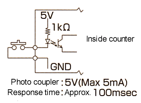
 Control Terminal Input Circuit
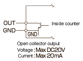
 Terminal Output Circuit
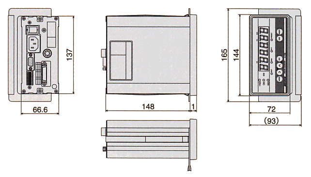
 Dimension of Digital Counters ( C-500, C-700 )
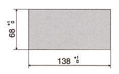
 Panel cutting dimensions ; Panel thickness ( t = 1.6 - 3.2mm )


 Displayed digits
 Selection of 10?m
